| |
Barnett Shale Development
Planning
The Company will rely heavily on the use of horizontal drilling
and 3D seismic to plan and execute development of its Barnett Shale
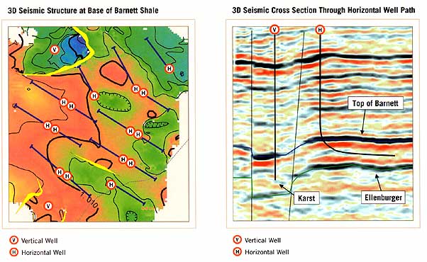
acreage position. A typical 3D seismic survey showing the structure
at the base of the Barnett Shale is depicted on the above left image.
Red indicates structurally higher position and blue represents
lower structural position. This survey demonstrates the presence
of both faults (yellow) and a karst feature at the northern edge
of the survey. Surface locations of both horizontal and vertical
wells and the corresponding horizontal well paths are shown. Horizontal
well paths are configured to avoid intersection with these faults
and karsts that can serve as conduits to the potentially water bearing
Ellenburger formation below the Barnett. Depending upon the size
of the area impacted by faults and karsts, vertical wells may be
drilled instead of horizontals. Horizontal well paths are also oriented
perpendicular to the projected direction of the hydraulically induced
fractures created during stimulation with slickwater (fresh water
with viscosity reducing additives) and sand proppant. These induced
fractures are designed to connect with and expand the natural fracture
system present within the Barnett Shale formation. The right image
above depicts the difference between the vertical and horizontal
well path in a cross-sectional view.
We believe an approach that effectively integrates
geologic information, 3D seismic data, and drilling, completion
and production data from Carrizo and competitor wells, is required
to maximize the productivity, reserves and ultimately the profitability
of the Barnett Shale.
|
|
|